Glass Melting Process
Melting
The typical melting furnace is a Six Port Cross Fired Regenerative furnace with a capacity of 500 tons per day. Cross fired regenerative furnaces have been built for very small and very large melting areas. The smallest units may be uneconomical, although in certain cases they may provide the only technologically possible route. The major sections of the furnace are melter refiner, working end, regenerators, and ports, and are constructed of specialized refractory material with an outside steel framework. The largest units are found in flat glass manufacture, where furnaces with total areas of 500m2 and above are found. The typical 500 ton melter has an area measuring 23m x 9.5m (218.5m2) with a glass depth of 1150mm.
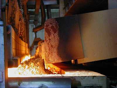
The batch mixture is delivered to the melting furnace where the batch is heated to approximately 1580°C (2875°F). Insulation, special airflow features, and combustion air heating enable the furnace to operate at maximum fuel efficiency with negligible pollutant emissions. The batch is melted by fossil fuels, natural gas, or fuel oil.
The melting furnace consists of refractory bricks, in both standard and special shapes, support, and binding steel, insulation, the fuel firing system, temperature sensors, and the necessary controls. The design of the furnace is adapted to meet the plant's specific tonnage goals.
From the melter the glass flows through the waist area, where stirrers homogenize the glass into the working end. The waist is a refractory lined canal that connects the melter to the working end.
Melter Combustion
A cross fired regenerative furnace uses regenerators to store waste heat that is contained in the exhaust gases that are developed during a firing cycle of the furnace. The waste heat is then used to preheat the combustion air during the next firing cycle, resulting in a considerable improvement in fuel economy.As an example, we will describe the firing cycles of a cross fired regenerative melting furnace. The first cycle will begin with firing from the North side of the furnace. The fuel, either natural gas or fuel oil is introduced to the furnace through several burners that are located under the ports. As the fuel enters the melter it is mixed with combustion air that has traveled through and has been pre heated by the regenerator. The fuel to air ratio and the total amount of fuel to each burner and port are very closely controlled. As the fuel air mixture enters the melter, the fuel is ignited by the intense heat of the melter and a continuous flame develops that will extend nearly the entire width of the melter. The combustion exhaust gasses leave the melter through the ports on the South side of the melter, make a 90° turn and flow downward through the South regenerator. Regenerators are refractory structures with an area of 11m x 3m and a height of 10m. Inside the regenerators, a matrix of refractory bricks is stacked from the bottom up to the port level. The bricks take on heat as the waste gasses pass through the openings in the brick matrix. At the bottom of the regenerator is a refractory lined exhaust flue that channels the exhaust gasses through a reversing valve to the chimney for discharge. The waste gas passing through the regenerator heats the brick (checkers) to 650°C at the bottom of the checker matrix and to 1320°C at the top of the matrix.
When the checkers of the South regenerator have reached their desired maximum temperature, the furnace reverses. This means that the fuel feed is stopped on the North side and started on the South side along with the reversal valve changing position so that the North exhaust flue is open to the chimney and the South exhaust flue is closed to the chimney and open to the supply of combustion air that can flow upward through the South regenerator, taking on heat, and combine with fuel from the South port burners to provide combustion to the melter.
A regenerative furnace changes it's direction of firing on a periodic basis, usually every 15 to 20 minutes, to enable it to recover some of the heat that is lost in the waste exhaust gasses and therefore to make it operate in a more efficient manner.
Refining
The refiner is an extension of the melter with an area of 13m x 9.5m (123.5m2). When all raw materials have been fully melted, large amounts of gases that remain in the glass can form bubbles, seeds, or blisters. The purpose of the refiner is to remove these gaseous inclusions.Working End
The working end is a separate refractory chamber with an area of 14m x 8.5m (119m2) and a glass depth of 1150mm. Glass flows through the canal, where it is stirred, into the working end for additional conditioning and to establish a laminar glass flow to the next furnace, the float bath furnace.The temperature conditioning, of the working end, cools the glass from a temperature of 1315°C (2400°F) at the entrance to 1065°C (1950°F) at the exit.